Calibration of Line Impedance Stabilization Networks (LISNs) / Artificial Mains Network (AMNs)

LISNs/AMNs are used to provide a standardized impedance for the device under test and to measure conducted interference emissions. As an experienced calibration and testing service provider in the field of electromagnetic compatibility (EMC) and electromagnetic immunity (EMI), we have many years of experience in dealing/working with LISNs/AMNs and LISN calibration.

Therefore, we know what is important and offer this service also to our customers.  With our LISN calibrations you also receive a conformity assessment and thus proof whether your devices comply with the manufacturer's specification, a standard or your individual specifications.

Artificial Mains Networks (AMNs) / LISN Calibration according to various standards:

For the testing of conducted interference emissions of DUTs, LISNs/AMNs have to fulfill the following functions:

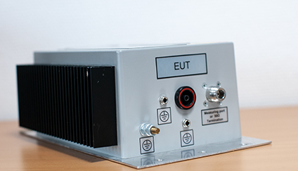
  • conduct interference emissions out of the DUT to the test port "receiver"
  • power supply of the equipment through connections with defined impedance
  • protect the supply network from possible interference emissions
  • filter possible interfering signals out of the supply network
Impedance as magnitude |Z| and Phase ∆φ(Z) of a V-LISN for band B and C from 150 kHz to 108 MHz according to CISPR 16-1-2:2014. (This allows a tolerance of ± 20 % for magnitude and ± 11,5° for phase.)

There are several types of LISNs/AMNs. The three most important types are listed below:

  • Delta-LISN
  • T-LISN
  • V-LISN
LISN 50/50/16 MIL/VG according to MIL-STD-461E from August 1999, MIL-STD-462D from September 2007

Furthermore, LISNs/AMNs vary in the design of the connectors. For a proper calibration the measurements must be corrected for the influence of the adapters of the type-N system of the vector network analyzer (VNA) to the connection system of the LISN/AMN. For this purpose two symmetrical adapters, respectively a combination of male and female as symmetrical as possible, must be used for the calibration. The measurement equipment for the following connection types is provided by us as standard:

  • 4 mm banana plugs with various distances
  • Schuko plugs (type F, CEE 7/4) or sockets (CEE 7/3)
  • IEC-60309-2 plug connectors for 16 A and 32 A
  • BNC
  • RJ45
  • various clamping systems
  • others on request

What do we calibrate?

In general, when calibrating LISNs/AMNs, the impedance of a port and the transmission between two ports are of interest. We are internationally accredited by the Deutsche Akkreditierungsstelle GmbH (DAkkS) within the ILAC Mutual Recognition Arrangement (ILAC MRA) for the measurement categories reflection, transmission and phase. Based on this measurement, the relevant parameter for the conformity assessment result:

  • Magnitude and phase of the impedance: |Z| and φ
  • Transmission as Voltage Division Factor (VDF)

The corresponding equations can be found at the end of this page.

We can determine the following values:

  • Impedance of the " EuT" terminal(s) under the following conditions, if applicable
    • "Receiver" with 50 Ω termination
    • The "receiver" can be switched to different paths, additionally using the internal 50 Ω termination by selecting another path to carry through to the "receiver" connection
    • Each with open and / or short-circuited "mains" terminal
  • Transmission from "EuT" to "receiver" ("insertion loss EUT-receiver")
    • "Mains" open
    • Minus the "internal impedance"
    • Usually as "Voltage Division Factor" (VDF) in dB
  • If required: transmission from "mains" to "receiver" ("isolation")
    • Usually as "Voltage Division Factor" (VDF) in dB
  • If required: transmission from "EuT" to "mains" and from "mains" to "EuT”
    • Usually as "Voltage Division Factor" (VDF) in dB
  • If requested, we can additionally determine the crosstalk between two paths
Schematic diagram of a setup for measuring the interference emissions of a DUT.

LISN Calibration – from the accredited measurand to the desired measurand

S-Parameter Sij

  • \[S_\mathrm{ij} = \frac{P_\mathrm{i}}{P_\mathrm{j}}\]

    Ratio of the power going into port j and the power coming out of port i.

Complex impedance Zij

  • \[Z_\mathrm{ij} = Z_0\frac{1+S_\mathrm{jj}}{1-S_\mathrm{ii}}\]

    With Z0 = 50 Ω of the impedance of the reference device

  • \[|Z_\mathrm{ij}| =\sqrt{\mathrm{Re}({ Z_\mathrm{ij}})^2+ \mathrm{Im}({ Z_\mathrm{ij}})^2}\\\] \[\newline\]

    Usual for LISN/AMN is the specification in magnitude Zij and phase φij

  • \[ \phi_\mathrm{ij} = \mathrm{tan}^{-1}\left(\frac{ \mathrm{Im}({ Z_\mathrm{ij}})}{ \mathrm{Re}({ Z_\mathrm{ij}})}\right)\]

    With Re and lm determining the real part and the imaginary part of a complex number

Transmission expressed as Voltage Division Factor „VDF

  • \[VDF_\mathrm{lin} =\frac{U_\mathrm{in}}{U_\mathrm{out}} =\frac{\sqrt{Z_\mathrm{ij}*P_\mathrm{j}}}{\sqrt{Z_\mathrm{ij}*P_\mathrm{i}}}\]

  • \[\\\]\[VDF_\mathrm{log}/\mathrm{dB} = 20 \log_{10} (VDF_\mathrm{lin})\]

More questions? We will gladly help you!